Our club recently acquired an RF coaxial switch from the estate of a fellow ham who is SK. The switch looked to be 1970’s vintage, is quite heavy & gave the impression of a very well designed piece of hardware, even before the cover was removed. The tags on the side were in two sections, the upper with part # 9652-5, 115V Actuator, and on the lower section part # 1998-5 RF Head SP5T. We had no paperwork or info on the switch and the original controller was not with the switch. Googling the part numbers & manufacturer turned up virtually no useful information. It also looked like it had been drop from top of a tower at one point in its life as the connector was pushed well down into the housing. The only thing to do was break into it & reverse engineer with the hopes of being able to give the old switch a second lease on life. In order to remove the cover, the first chore was to remove the 6-pin connector, which was pushed down into the case and had to be cut out with a Dremel tool & a few cutting discs.
Once the connector was removed, the cover was still difficult to remove as it had several dents in the side. I was expecting to see some arrangement of relays to do the switching, but was surprised to see a motor, gearbox & rotary switch. Close inspection showed that the top actuator separated from the lower RF head with four small 4-40 bolts in slots, that had the heads mangled, and looked as if it was part of an adjustment to align the RF switch with the AC rotary switch. The bolts were removed with the help of a pair vice grips, but resulted in the total destruction of the bolts.
Once the two parts were separated, it was easier to reverse engineer the electrical and put together a rough diagram, which also helped make more sense of the mechanical. Images of the schematics I made are at the bottom of this post. There is also a solenoid in series with the motor which pulls in an arm and locks a pawl gear in place which acts like a clutch and engages the motor. The motor turns the AC rotary switch & the RF switch until a space in the AC rotary switch moves over the requested position. This breaks the current through the motor & the solenoid which releases, allowing to motor to spin freely while the RF switch snaps into position of the requested antenna.
Some basic testing proved that the motor & solenoid were still working which made the switch worth saving. The DIY controller was completed and a new 8 pin connector replaced the original 6 pin on the switch. A 30 foot length of rotor control cable used with matching 8 pin females on each end as the control line. Luckily, the rotor cable had the same colors that was used internally in the RF switch, so matching colors were able to be used from the push button on the controller right through to the AC rotary switch in the Actuator section of the switch.
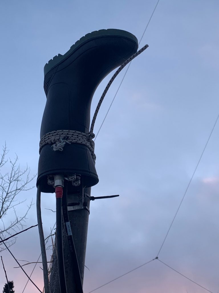
The switch was installed on Nov 28, 2022 while it was a relatively mild -15 Celsius. I was really impressed with Naz’s standard Newfie Weather Head for extra protection from the elements. The 10m Loop was connected to the switch (Coax with Red tape) & operation was confirmed with a QSO to Brazil.
Below are the Diagrams I drew as I worked on this RF switch. The first diagram is the wiring as it appeared on the original 6-pin connector which had to be destroyed.
The diagram below is the inside of the Actuator, now showing the new 8-pin connector. The diagram shows the switch in Position 1 (red wire). If antenna 4 is selected on the controller, 115 VAC is applied to the green wire. Position 4 contact is making with the neutral which starts the motor, pulls in the solenoid, engaging the clutch. The motor continues turning the AC rotary RF switch until the gap in the AC rotary switch center conductor falls over the green contact, opening the circuit. This drops the solenoid, which disengages the clutch, allowing the RF switch to snap into place. The gap can be seen in the picture of the AC rotary switch above, difficult to pick out as it is on the very bottom of the center copper disc.
The DIY controller as completed. All voltages in the controller and in the Actuator head are 115 VAC and provides voltage to the appropriate contact in the AC rotary switch in the head to move to that position.
This entire rebuild took about 2 weeks of spare time to figure out the electrical & mechanics so I put this post together to help out anyone else that comes across one of these wonderful old beasts and wants to give it some TLC. If this post helped you out with reviving one, our you just found it interesting, leave a comment below.
73, de VO2GO
4 responses to “TransCo RF Switch Rebuild”
As usual, Awesome job Glen!
Ben
Great work Glen. Appreciate all the work you do for local hams and amateur radio in general.
Guy
Very professional work, and writeup.
Thanks Glen for all you do.
Darryl
Thanks for the comments. The switch was installed today & this post updated with picture of Naz’s awesome DIY weather head.